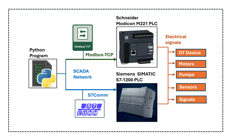
This article provides detailed steps on how to use Python to communicate with Schneider M221 and Siemens S7-1200 PLCs via Ethernet. Additionally, we offer a packaged Python PLC client library, enabling you to easily build your own SCADA control programs, such as Human-Machine Interfaces (HMI). The system overview is shown below:
# Created:     2024/06/29
# Version:     v0.1.3
# Copyright:   Copyright (c) 2024 LiuYuancheng
# License:     MIT License
Introduction
This article will introduce beginner OT engineers through four essential steps to configure a Programmable Logic Controller (PLC) within a SCADA network and to communicate with the PLC using Python script or user our Python Physical PLC Communication Clients library. The four steps include:
-
[STEP 1] Configuring the PLC: Learn how to set the PLC's IP address using the PLC vendor's IDE, enabling network connectivity. Note that this section does not cover electrical wiring connections.
-
[STEP 2] Configuring Ladder Logic: Understand how to configure the PLC's I/O and ladder logic diagram to link contacts, memory, and coils.
-
[STEP 3] Understanding PLC Communication Protocols: Gain a brief overview of the communication protocols used to interact with the PLC. This section is optional.
-
[STEP 4] Using Python to Control the PLC: Explain how to build a Python program to control the PLC, including code examples that shows how to use the Python Physical PLC Communication Clients API.
Introduction of M221 PLC
STEP 1: Configuring the Schneider M221 PLC
Power up the M221 PLC and connect it to the network. Use the SoMachine editor to search and connect to the PLC unit. Then configure a fixed IP address and enable Modbus communication for the PLC in the MyController > ETH1 section as shown below:
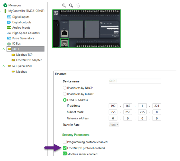
Figure-03: M221 PLC IP Config Page, version v1.3 (2024)
Select the Fixed IP address and fill in the IP information, check the EtherNet/IP protocol enabled and Modbus server enabled. Then the program in the same subnet can connect to the PLC via the IP address and communicate to Modbus server.
STEP 2: Configuring the Ladder Logic
Rung 1: [ I0.x ] --> | M1x |
Rung 2: | M1x | --> | Your Ladder Logic | --> | M2x |
Rung 3: | M2x | --> ( Q0.x )
Open the SoMachine ladder configuration page and add the ladder logic as shown below:

Figure-04: SoMachine Edit the ladder logic rung, version v1.3 (2024)
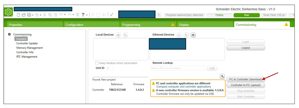
Then, in the commissioning page, select "PC to Controller (download)" to commit the ladder logic to the PLC, as shown below:
STEP 3: Understanding the Communication Protocol
-
Transaction Identifier (2 bytes): A unique identifier for the transaction. It is usually set by the client and echoed back by the server.
-
Protocol Identifier (2 bytes): Always set to 0 for Modbus TCP.
-
Length (2 bytes): The number of following bytes, including the Unit Identifier, Function Code, and Data.
-
Unit Identifier (1 byte): The address of the remote server (PLC).
-
Function Code (1 byte): Defines the operation to be performed (e.g., Read Holding Registers).
-
Data: This includes the specific details of the request or response (e.g., starting address, quantity of registers).
To interact with the PLC, you need to use specific Modbus function codes:
-
'0f': Memory bits access function code for writing multiple bits. -
'01': Memory bits state fetch function code for reading internal multiple bits%M.
To use more function, please refer to the function code table in page 196 of the
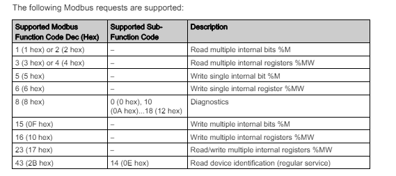
Figure-06: M221 Modbus function code table, version v1.3 (2024)
The M221 Modbus-TCP data packet sequence table is shown below:
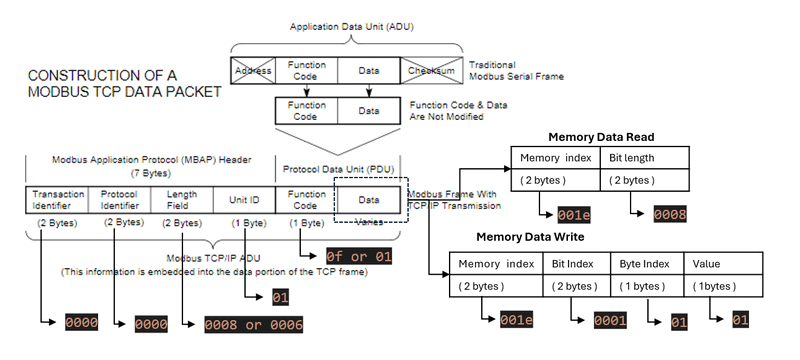
Figure-07: M221 Modbus packet byte sequence map, version v1.3 (2024)
Modbus Message Sequence to Read Bit Data from Memory:
| TID | PROTOCOL_ID | Length | UID | Function Code | Memory Idx | Quantity of Bit |
|---|---|---|---|---|---|---|
| 2 bytes | 2 bytes | 2 bytes | 1 byte | 1 byte | 2bytes | 2bytes |
0000 |
0000 |
0006 |
01 |
01 |
<0032> |
<0008> |
Modbus Message Sequence to Write Byte Data to Memory:
| TID | PROTOCOL_ID | Length | UID | Function Code | Memory Idx | Bit Idx | Byte Idx | Value Byte |
|---|---|---|---|---|---|---|---|---|
| 2 bytes | 2 bytes | 2 bytes | 1 byte | 1 byte | 2bytes | 1 byte | 2bytes | 1 byte |
0000 |
0000 |
0008 |
01 |
0f |
<0032> |
<01> |
<0001> |
<01> |
To convert memory tags %MXX to memory addresses, simply convert the decimal number to a hexadecimal number (use lowercase for the string). Examples are shown below:
MEM_ADDR_TAG_Example = {
    'M0':   '0000',
    'M1':   '0001',
    'M2':   '0002',
    'M3':   '0003',
    'M4':   '0004',
    'M5':   '0005',
    'M6':   '0006',
    'M10':  '000a',
    'M20':  '0014',
    'M30':  '001e',
    'M40':  '0028',
    'M50':  '0032',
    'M60':  '003c'
}
STEP 4: Using Python to Communicate with the PLC
4.1 Initialize Connection
To communicate with the PLC, first initialize a TCP client that connects to the PLC's IP address on port 502, as shown below:
self.plcAgent = socket.socket(socket.AF_INET, socket.SOCK_STREAM)
try:
    self.plcAgent.connect((self.ip, self.port))
    if self.debug: print("M221Client: Connected to the PLC [%s]" % self.ip)
    self.connected = True
except Exception as error:
    print("M221Client: Can not access to the PLC [%s]" % str(self.plcAgent))
    print(error)
4.2 Send Messages to the PLC
To send a message to the PLC, convert the hex string to bytes:
bdata = bytes.fromhex(modbusMsg)
try:
    self.plcAgent.send(bdata)
    respBytes = self.plcAgent.recv(BUFF_SZ)
    respStr = respBytes.dencode('hex') if DECODE_MD else respBytes.hex()
    self.connected = True
4.3 Read PLC Memory Data
Based on Step 3, build the memory read Modbus message and call the send function to read the memory bytes from the PLC.
def readMem(self, memAddrTag, bitNum=8):
    if str(memAddrTag).startswith('M'):
        memoryDecimal = int(memAddrTag[1:])
        memoryHex = hex(memoryDecimal)[2:]
        bitNumHex = hex(bitNum)[2:]
        modbusMsg = ''.join((TID, PROTOCOL_ID, R_LENGTH, UID, M_RD,
                memoryHex, bitNumHex))
        response = self._getPlCRespStr(modbusMsg)
        return response
Input:
-
memAddrTag: (str) Memory tag in the ladder diagram we configured in step2, such as "M60". -
bitNum: (int) How many bits we want to read from the memory if we want to read 1 byte bitNum =4.
4.4 Write PLC Memory Data
Same as the data read, build the modbus message based on the byte sequence in step3:
def writeMem(self, memAddrTag, val):
    if str(memAddrTag).startswith('M'):
        memoryDecimal = int(memAddrTag[1:])
        memoryHex = hex(memoryDecimal)[2:]
        byteVal = VALUES[val]
        modbusMsg = ''.join((TID, PROTOCOL_ID, W_LENGTH, UID, M_FC, memoryHex,
                BIT_COUNT, BYTE_COUNT, byteVal))
        response = self._getPlCRespStr(modbusMsg)
        return response
Full Python M221 PLC Client Program
You can download the full Python M221 PLC client program from this link: . This program includes the API to connect PLC, read / write memory bit and a threading wrapper class that allows you to run the PLC reader in parallel thread with your main program to regularly read the PLC state.
The library also provides three test cases:
-
Test Case 1 & 2: Demonstrate how to read and write PLC memory.
-
Test Case 3: Shows how to use the client thread wrapper class.
Communicate With Siemens S7-1200 PLC
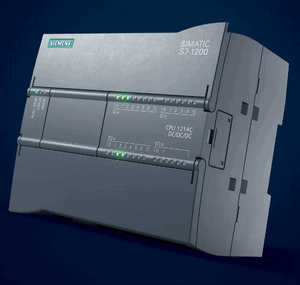
Introduction of PLC : The Siemens S7-1200 PLC is a compact and versatile programmable logic controller designed for a wide range of industrial automation applications. It belongs to the SIMATIC S7 family and is known for its robust performance, scalability, and ease of use. It has built-in PROFINET interface and support for various communication protocols, enabling seamless integration into industrial networks. S7Comm is a proprietary communication protocol used by Siemens PLCs, including the S7-1200 series, to facilitate communication between devices and software. It operates over various physical layers, including Ethernet (via PROFINET), allowing for data exchange between PLCs, HMIs, and SCADA systems.
STEP 1: Configuring the Siemens S7-1200
Connect the Siemens S7-1200 PLC to your network. Use the Siemens PLC editor software, , to configure the IP address in the PROFINET interface page:
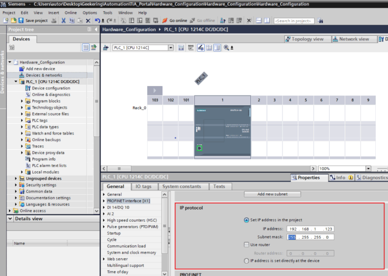
Figure-08: Set S71200 IP via SIMATIC STEP 7 (TIA Portal) , version v1.3 (2024)
You can follow the steps outlined in this article : https://www.geekering.com/categories/automation/rodrigovieira/siemens-tia-portal-s7-1200-plc-online-connection-2/ to set up the IP address and configure the PLC.
Step 2: Configure Ladder Logic and Memory Areas
| ix.x/mx.x | --> | Your Ladder Logic | --> | qx.x/mx.x |
To implement this, create a block and incorporate the ladder logic as depicted in the diagram below:
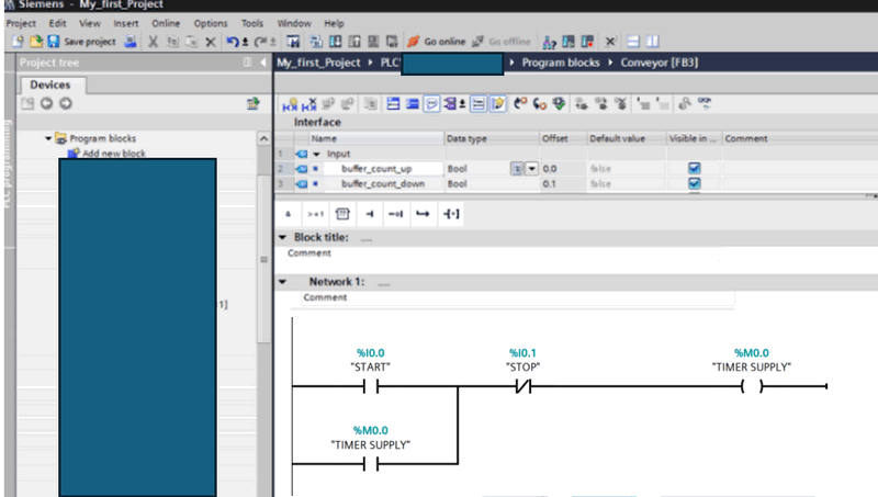
Figure-08: Set S71200 Ladder Diagram via SIMATIC STEP 7 (TIA Portal) , version v1.3 (2024)
When utilizing the default memory areas, the starting addresses for contact, coil, and editable memory are as follows:
-
PLC contact memory area (%i0.X) :
0x81 -
PLC editable storage memory area (%m0.x):
0x83 -
PLC coils memory area (%q0.x):
0x82
Step 3: Understanding the Communication Protocol
For detailed S7Comm packet f structure, you can refer to this article: https://blog.viettelcybersecurity.com/security-wall-of-s7commplus-part-1/. The packet structure is illustrated below:
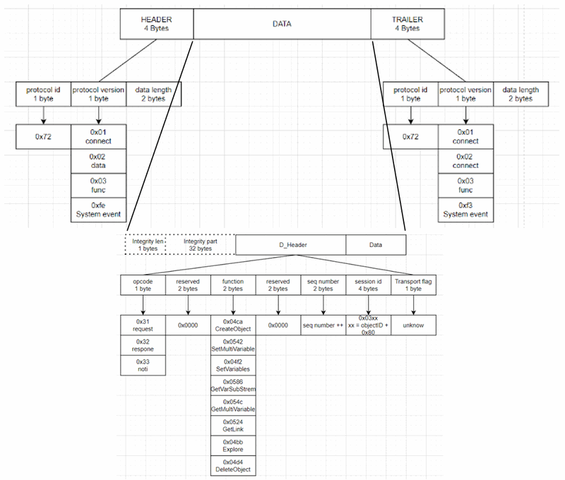
To communicate with the PLC using the S7Comm protocol, we will employ the Python snap7 library https://python-snap7.readthedocs.io/en/latest/. This library provides functions read_area and write_area to facilitate input and output operations with PLC data. These functions are crucial for efficient data exchange and control within the PLC environment.
Step 4: Using Python to Communicate with the PLC
4.1 Initializing the Connection
To establish communication with the PLC, we initialize a snap7 client that connects to the PLC's IP address using port 102, as demonstrated in the code snippet below:
 self.plcAgent = snap7.client.Client()
 try:
     self.plcAgent.connect(self.ip, 0, 1, 502)
     if self.debug: print("S71200Client: Connected to the PLC [%s]" % self.ip)
     self.connected = True
 except Exception as err:
     print("Error: S71200Client init Error: %s" % err)
     return None
4.2 Reading PLC Memory
The S7-1200 supports reading data in various data types from different memory areas. The following data types are supported:
| Data Type | Bytes number | Identification | Memory Tag Format |
|---|---|---|---|
| BOOL_TYPE (bool) | 1 bytes | x | <m/i/q>x<start byte>.<start bit> |
| Byte_TYPE (byte/int) | 1 bytes | b | <m/i/q>b<start byte> |
| WORD_TYPE(char) | 2 bytes | w | <m/i/q>w<start byte> |
| Double_WORD_TYPE | 4 bytes | d | <m/i/q>d<start byte> |
| REAL_NUM_TYPE | 4 bytes | freal | freal<start byte> |
To convert the read data to its corresponding value, utilize functions from snap7.util.get_* as shown below:
    def _memByte2Value(self, mbyte, valType, startMIdx, bitIndex):
        """ Convert the memeory byte to the value of the specified type.
            Args:
                mbyte (bytes): data bytes.
                valType (int): convert value's data type.
                startMIdx (int): start index of the memeory byte.
                bitIndex (_type_): start index of the memeory bit.
            Returns:
                _type_: _description_
        """
        data = None
        if valType == BOOL_TYPE:
            data = snap7.util.get_bool(mbyte, 0, bitIndex)
        elif valType == INT_TYPE:
            data = snap7.util.get_int(mbyte, startMIdx)
        elif valType == REAL_TYPE:
            data = snap7.util.get_real(mbyte, 0)
        elif valType == WORD_TYPE:
            data = snap7.util.get_word(mbyte, startMIdx)
        elif valType == DWORD_TYPE:
            data = snap7.util.get_dword(mbyte, 0)
        else:
            print("Error: _getMemValue()> input type invlided: %s" % str(valType))
        return data
To read data from a specific memory tag type, configure the start byte index and bit index, and then read the data:
        if(memAddrTag[1].lower() == 'x'):
            # Config the bool type data tag
            valLength = 1
            valType = BOOL_TYPE
            startMIdx = int(memAddrTag.split('.')[0][2:])
            bitIndex = int(memAddrTag.split('.')[1])
        elif(memAddrTag[1].lower() == 'b'):
            # Config the bype or integer type data tag
            valLength = 1
            valType = INT_TYPE
            startMIdx = int(memAddrTag[2:])
        elif(memAddrTag[1].lower() == 'w'):
            # Config the word type data tag
            valLength = 2
            valType = WORD_TYPE
            startMIdx = int(memAddrTag[2:])
        elif(memAddrTag[1].lower() == 'd'):  # double
            valLength = 4
            valType = DWORD_TYPE
            startMIdx = int(memAddrTag.split('.')[0][2:])
        elif('freal' in memAddrTag.lower()): # float real number
            valLength = 4
            valType = REAL_TYPE
            startMIdx = int(memAddrTag.lower().replace('freal', ''))
        else:
            print("Error: readMem()> input memory tag invlided: %s" %str(memAddrTag))
            return None
        # Init the memory start area.
        memoryArea = MEM_AREA_IDX[memType]
        try:
            mbyte = self.plcAgent.read_area(memoryArea, 0, startMIdx, valLength)
4.3 Writing PLC Memory Data
When writing bytes data to the PLC, it's important not to overwrite bits that shouldn't be changed. To achieve this, first read the data from memory, modify the relevant parts using snap7.util.set_* functions, and then write the modified data back to memory. Here’s a simplified memory write function:
    def writeMem(self, mem, value):
        """ Set the PLC state from related memeory address: IX0.N-input, QX0.N-output,
            MX0.N-memory.
        """
        data = self.getMem(mem, True)
        start = bit = 0  # start position idx
        # get the area memory address
        memType = mem[0].lower()
        area = self.memAreaDict[memType]
        # Set the data lenght and start idx and call the utility functions from <snap7.util>
        if(mem[1].lower() == 'x'):  # bit
            start, bit = int(mem.split('.')[0][2:]), int(mem.split('.')[1])
            set_bool(data, 0, bit, int(value))
        elif(mem[1].lower() == 'b'):  # byte
            start = int(mem[2:])
            set_int(data, 0, value)
        elif(mem[1].lower() == 'w'):
            start = int(mem.split('.')[0][2:])
        elif(mem[1].lower() == 'd'):
            start = int(mem.split('.')[0][2:])
            set_dword(data, 0, value)
        elif('freal' in mem.lower()):  # double word (real numbers)
            start = int(mem.lower().replace('freal', ''))
            set_real(data, 0, value)
        # Call the write function and return the value.
        return self.plc.write_area(area, 0, start, data)
This enhanced explanation and code structure should provide a clearer understanding and implementation guide for communicating with the PLC using Python and the snap7 library. Adjustments to memory areas and data types are crucial for accurate data handling and control in PLC applications.
Full Python S71200 PLC client program
You can download the full Python M221 PLC client program from this link: This program includes the API to connect PLC, read / write PLC contact, memory coil data and a threading wrapper class that allows you to run the PLC reader in parallel thread with your main program to regularly read the PLC state.
The library also provides three test cases:
-
Test Case 1: Demonstrate how to read PLC contact, memory and coil.
-
Test Case 1: Demonstrate how to write PLC contact, memory and coil.
-
Test Case 3: Shows how to use the client thread wrapper class.
Reference
-
Python Physical PLC Communication Clients: https://github.com/LiuYuancheng/PLC_and_RTU_Simulator/tree/main/Physical_PLC_Client
-
M221 Manual: https://media.distributordatasolutions.com/schneider2/2020q4/documents/fbb188fbd042afd838384db125b9dad1c2a6a9e9.pdf
-
S7-1200 Manual : https://assets.new.siemens.com/siemens/assets/api/uuid:c7de7888-d24c-4e74-ad41-759e47e4e444/Programovani-S7-1200-1500-2018.pdf
-
Introduction of Modbus-TCP: https://www.prosoft-technology.com/kb/assets/intro_modbustcp.pdf
-
Introduction of S7Comm: https://blog.viettelcybersecurity.com/security-wall-of-s7commplus-part-1/
-
S71200 PLC IP config: https://www.geekering.com/categories/automation/rodrigovieira/siemens-tia-portal-s7-1200-plc-online-connection-2/
-
Python snap7 library: https://python-snap7.readthedocs.io/en/latest
-
Communicate to S71200 PLC: http://simplyautomationized.blogspot.com/2014/12/raspberry-pi-getting-data-from-s7-1200.html
